A computer from scratch - ADDing more functionality
September 12, 2015 by Marco Cecconi
September 12, 2015 by Marco Cecconi
In the first installment of "A computer from scratch", I've built a NAND gate. In the third part I've built NOT, AND and OR circuits and I've also introduced the 4011 CMOS NAND gates, which I'm using instead of a bunch hand built, transistor-based NANDs (because hey, that's a lot of wiring, but not a lot of new insight). NOT, AND and OR circuits are built with one, two and three NANDs respectively.
In this part, I'll first build a XOR gate, which uses four NANDs, and then a half adder, which uses six NANDs.
At that point I'll build a full adder, but I'll start using pre-build XORs and ANDs for that, because that would be too many components to wire.
All these build were easy, I've done them in minutes (well, without counting the time to find the right resistors but, ...yeah)
A NAND=based implementation of XOR can be built with four NANDs using the following identity (keep in mind that NOT X OR NOT Y = X NAND Y):
A XOR B = (A AND NOT B) OR (B AND NOT A)
        = NOT (A NAND NOT B) OR NOT (B NAND NOT A)
        = NOT (A NAND B NAND B) OR NOT (B NAND A NAND A)
        = (A NAND B NAND B) NAND (A NAND B NAND A)
Which can be implemented via this gate logic

I've implemented this with a 4011 and the following plan
The build was easy and looked like this
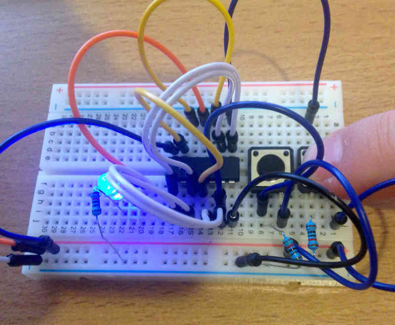
Half adders start to become more interesting, they do sums! They have 2 ins and 2 outs and respect the following truth table:

What they do is, given two bits (one in A and the other in B) they return the sum in S and the eventual overflow in C (for carry)
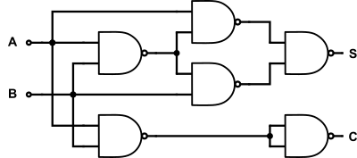
It's evident from the truth table that, S = A XOR B and C = A AND B and thus a half adder can be implemented via the following gate logic:

Since I had the previous build handy, I added an AND gate to the XOR gate I already had and got the following NAND-based half adder:
When laid out as a circuit and on a breadboard plan it looks like this
As you can see, stuff is getting complicated here! Here's the build
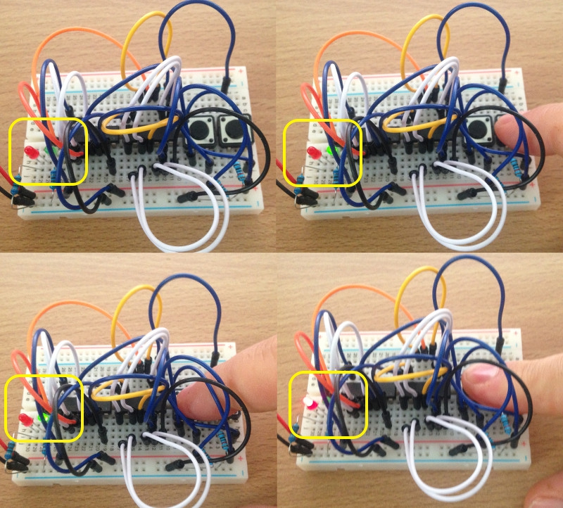
The board is getting pretty crowded...
A full adder is a 3-in 2-out circuit which works like an adder. In addition to it, it has a carry in input, as well as output (so it adds 3 bits). It's a very important feature! Unfortunately, this makes the circuit much more complex. Here's the truth table
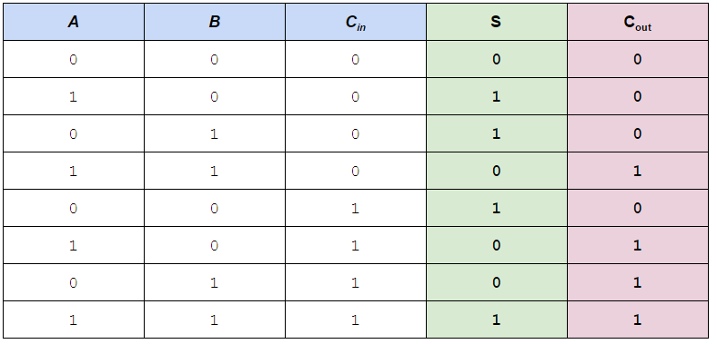
By looking at the parts where C_in has different values separately, I could recognize these identities
S     = C_in XOR (A XOR B)
C_out = C_in AND (A XOR B) OR (A AND B)
Reasoning on these, and looking at the half adder logic, if we start by connecting A and B to a half adder, we have in output
S_h1 = A XOR B
C_h1 = A AND B
We can then connect another half adder to Cin and Sh1 and obtain
S_h2 = S_h1 XOR C_in = C_in XOR (A XOR B)
C_h2 = S_h1 AND C_in = C_in AND (A XOR B)
Therefore Sh2 is the S output of the full adder, and we can also obtain Cout easily by ORing the two partial carries.
C_h1 OR C_h2 = A AND B OR C_in AND (A XOR B) = C_out
In summary, we need two half adders and an OR gate to build a full adder:
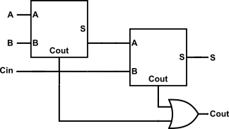
By substituting in the plans we already have for half adders and OR gates, we can derive a 15 NAND gate circuits. It's a tad too complex, so I'm cheating again by introducing three new friends: a 4-AND IC, a 4-OR IC and a 4-XOR IC.
This will allow me to use actual AND/OR/XOR gates in the diagram instead of NANDs. With this improvement, the diagram looks like this (stolen from Wikipedia):

As you can see, only 2 XORs, 2 ANDs and 1 OR are necessary to build this. But first, let me introduce my new chips.
The 4070 is similar to a 4011 but performs four XORs instead of four NANDs. Its pinout is the following:
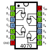
A1 and B1 will contain A and B; A2 and B2 will contain C_in and A XOR B, which we can pick up from Q1. The output of this second gate is the sum S
The next component I'll use is a 74HC08, which is performs 4 ANDs. It's not from the 4000 series but from the 7400 series. The only difference I can see is the layout of the inputs. In this case it looks like this:
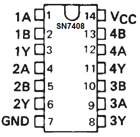
Following our diagram, we'll connect A and B to 1A and 1B; C_in and A XOR B (which is in Q1 from before) to 2A and 2B respectively.
The 4071 is a 4000 series 4 OR gate. It's pinout is similar to the 4011 and 4070 IC I used before.
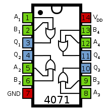
We need to OR the two partial carries coming out of the AND gate, and so we'll connect 1Y and 2Y to A1 and B1 and get C_out in Q1.
Overall the circuit looks like the following schematic. You can download a better looking PDF as well.
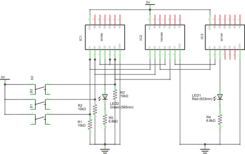
Note that I've deliberately left the top side of of the IC without any connection, beyond power. This will allow me, with relatively little work, to reuse this circuit to implement a second adder in the next part of this blog series. The breadboard plan is the following:
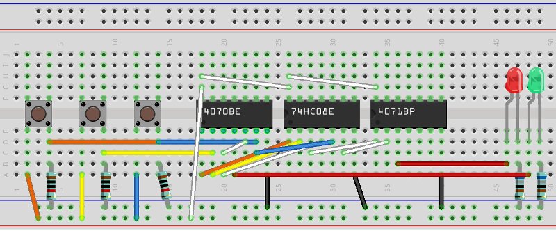
The three switches are A, B, and C_in, respectively. The red led is C_out and the green led is S.
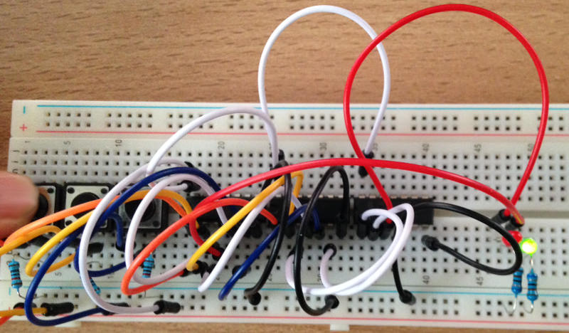
It works! It's a small thing but it's the first circuit I've built which actually does "something" not trivial. Before I started I had not figured out that addition and carry can be expressed as a truth table. Now I know, and my circuit does (very very simple) sums. I'm satisfied.
The next steps will be to build a 2-bit "ripple carry" adder and start investigating multiplexers. With those I will be very close to my next big step: building an ALU.
I am the Chief R&D at BaxEnergy, developer, hacker, blogger, conference lecturer. Bio: ex Stack Overflow core, ex Toptal core.
Read moreDecember 27, 2024 by Marco Cecconi
TDD can’t guarantee zero-defects. Let us debunk this software development myth.
Read moreMarch 12, 2023 by Marco Cecconi
Stack Overflow could benefit from adopting a using conversational AI to provide specific answers
Read moreOctober 15, 2021 by Marco Cecconi
Multiple people with my name use my email address and I can read their email, chaos ensues!
Read moreSeptember 29, 2021 by Marco Cecconi
After years of building, our top-notch consultancy to help start-ups and scale-ups create great, scalable products, I think it is high time I added an update to how it is going and what's next for us.
Read moreFebruary 03, 2021 by Marco Cecconi
A lesson in building communities by Stack Overflow's most prominent community manager emeritus, Shog9
Read moreWe can say that Mr. Robot is having a moment. The main character was one of the top choices and thus is perhaps the most/least realistic/annoying/inspiring portrayal of what it’s like to be a computer programmer today.
Read more…